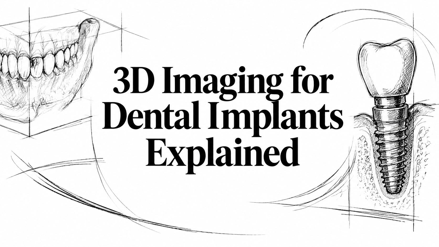
You're missing a back tooth, but the gap looks small in the mirror. Your flipper or partial denture gets you through meals, and you're wondering whether an implant would really make a difference. Then your dentist recommends a three-dimensional scan, and a new question comes up: what can that picture tell you about getting a natural-looking tooth without hurting a nerve or the sinus?
Why Implant Planning Starts With the Inside of the Jaw
The visible gap is only part of the problem. After a tooth is lost, neighboring teeth can tilt toward the space, the opposing tooth can drift, and you may start chewing more on the other side. Under the gum, the ridge that supported the tooth can gradually lose height and width.
That matters even when the missing tooth doesn't show when you smile. A narrower ridge can make replacement more complicated, while more extensive tooth and bone loss can reduce support for the cheeks and lips. A removable tooth fills the visible space, but it doesn't tell your dentist what bone remains underneath.

Looking beneath the gap
A standard dental film helps identify obvious disease and shows the general relationship between teeth and bone. But a flat image can't directly answer a key implant question: is the ridge wide enough to surround an implant in the position the crown needs?
Cone-beam computed tomography, or CBCT, provides cross-sectional views of the jaw. Think of cutting a loaf of bread. Looking at the loaf from the side tells you its outline, but looking at each slice reveals its shape throughout.
The NCBI Bookshelf overview of dental CBCT describes how this spatial information supports assessment of ridge dimensions and nearby anatomy when selecting implant position, dimensions, and angulation. That's a planning advantage, not a promise that surgery will be complication-free.
A replacement tooth needs room beneath the gum, not just room between the neighboring crowns.
If you're considering treatment, understanding who is a good candidate for dental implants starts with both your oral health and the foundation available for replacement. The useful outcome isn't an impressive picture. It's a tooth that looks right, functions comfortably, and respects the surrounding jaw.
What a CBCT Scan Shows Beyond a Flat X-Ray
A CBCT scanner rotates around your head and reconstructs the jaws as a three-dimensional volume, rather than one overlapping picture. A panoramic film is like a shadow on a wall. CBCT lets the dentist examine the object from different directions and look through it in slices.
A systematic review of digital implant planning explains how cross-sectional imaging supports assessment of bone height, width, volume, and angulation. In one comparison cited by that review, mean angular deviation was 4.8° with virtual planning and guided surgery versus 9.8° with freehand insertion, a finding about placement direction rather than a guarantee of healing or appearance.
The anatomy your dentist checks
The planner is not only looking for a bright patch of bone. Each proposed implant site requires a closer examination.
- Bone height: The dentist measures from the top of the ridge toward the nerve canal or sinus floor. This helps establish how much vertical room is available.
- Bone width: A cheek-to-tongue cross-section shows whether the implant can remain inside the bone walls, rather than extending through a thin outer surface.
- Ridge shape and angulation: A ridge can lean even when the gum looks level. Its slope affects whether an implant can support a crown that emerges naturally.
- Lower-jaw landmarks: The inferior alveolar canal contains the nerve pathway, while the mental foramen is an opening where a nerve branch exits toward the lip and chin.
- Upper-jaw sinus boundaries: The sinus floor and nearby walls help define the available space above an upper back-tooth site.
- Neighboring roots: Cross-sections separate roots that can overlap on a flat film, helping the dentist evaluate the proposed drilling path.
What the picture doesn't settle
The image doesn't establish whether your gums are inflamed, how your teeth contact during chewing, or how your medical history affects treatment. Those questions still require examination and conversation. Metal fillings, crowns, and existing implants can also create streaks that obscure an otherwise useful view.
For appearance, the important connection is between the bone underneath and the tooth you'll see above it. An implant that fits the ridge but points the crown toward the tongue may not provide the restorative result you want. The table gives an at-a-glance comparison of what each image contributes.
Panoramic X-ray versus CBCT for implant planning
| Planning question | Panoramic X-ray | CBCT |
|---|---|---|
| Bone height at the site | Estimated from an overlapping shadow | Measured on a cross-section |
| Bone width of the ridge | Not shown directly | Measured from cheek side to tongue side |
| Ridge shape and angulation | Inferred | Seen in three planes |
| Inferior alveolar nerve and mental foramen | Approximate location | Distance from the proposed implant visible |
| Maxillary sinus floor | Overlapping outline | Floor and nearby walls shown |
| Neighboring tooth roots | Can overlap on the film | Separated in cross-section |
| Link to a surgical guide | Not produced from the film alone | Volume can be merged with a digital impression |
How Accurate Implant Measurements Need to Be
Seeing the jaw clearly matters only if the measurements are useful for selecting implant length and width. A small average error is reassuring, but it doesn't mean every measurement in every mouth is exact.
The 2025 systematic review and meta-analysis of low-dose CBCT measurements included 13 studies and 81 samples and reported a pooled planning error of −0.24 mm, with a 95% confidence interval from −0.52 to 0.04 mm. The negative value means a slight overall tendency to underestimate the reference measurement, while the interval places the average error close to zero.
Why a close measurement still needs a buffer
The same review discusses broader published measurement errors of 0.19 to 1.27 mm and evidence supporting a 2 mm safety margin near important anatomy. The practical lesson is that your dentist shouldn't plan an implant to finish exactly at a nerve boundary just because software can display that distance.
Think of cutting food beside something you mustn't touch with the knife. Knowing where the boundary lies helps, but leaving space is safer than relying on the line alone. In surgery, that buffer also has to accommodate differences between the planned and achieved implant position.
A clinical assessment of implant planning and anatomical safety discusses an at least 1.7 mm vertical safety margin for implant selection in the posterior mandible and reports 96 postoperative CBCT images without injuries to vital anatomical structures. That series doesn't establish that the scan alone prevented complications, and nerve contact can still cause numbness, pain, or altered sensation.
CBCT accuracy and safety margins used in implant planning
| Measure | Reported figure | What it means for the patient |
|---|---|---|
| Low-dose planning error, pooled | −0.24 mm, 95% CI −0.52 to 0.04 | Average measurement sits close to the reference |
| Broader CBCT measurement error | 0.19 to 1.27 mm | Device, resolution, and artifacts can affect measurements |
| Margin near critical anatomy | About 2 mm | Leave protective clearance rather than placing against the boundary |
| Posterior mandible vertical margin | At least 1.7 mm | Preserve space above the nerve when choosing length |
| Guided surgery, entry point | About 1.2 mm mean deviation | Placement can differ from the virtual plan |
| Guided surgery, angulation | About 3.5° in one summary; 4.8° in another | Those reports describe smaller deviations than the approximately 9.8° freehand comparison |
Measurement error isn't placement error
A scan can measure the bone closely while the surgery still finishes slightly away from the planned position. These are different sources of uncertainty, not interchangeable accuracy scores.
For the patient, useful precision means choosing an implant that suits the bone present. If the ridge is too thin, the dentist can reconsider the implant or discuss bone grafting for dental implants before drilling begins. Changing a plan early is a benefit of imaging, not a failure of treatment.
Radiation Dose and When the Scan Is Worth It
Reported dental CBCT effective doses range from approximately 10 to 1,000 microsieverts, roughly equivalent to 2 to 200 panoramic radiographs, according to a review of CBCT protocols for implant assessment. That wide range reflects differences in the machine, field of view, voxel size, and exposure settings.
Dental CBCT isn't the same examination as a full medical CT of the head, but it generally involves more exposure than a single panoramic image. It should answer a clinical question, not be added because the equipment is available.
Match the scan to the question
Field of view means the area included in the scan. A small field focused on an implant site generally exposes less tissue than a larger examination covering an entire arch. It can also help the clinician concentrate image detail where it's needed.
Voxel size describes the tiny volume elements used to reconstruct the image. Choosing the finest setting automatically isn't the same as choosing the most appropriate examination. Conversely, reducing exposure too aggressively can create noise that makes anatomical borders harder to identify.
Practical rule: Use the smallest field that includes the surgical region, with enough image quality to answer the planning question.
What changes the dose of an implant CBCT
| Setting | Typical effect | Planning takeaway |
|---|---|---|
| Reported effective dose | About 10 to 1,000 μSv | Roughly 2 to 200 panoramic radiographs |
| Field of view | Smaller fields expose less tissue | Cover only the surgical region |
| Voxel size | Finer voxels are not always safer | Match resolution to the anatomy being measured |
| Aggressive dose reduction | Can add noise | Noise can hide nerve or sinus borders |
| Metal in the field | Streak artifacts | Existing crowns and implants can obscure edges |
When the extra information matters
The benefit is particularly clear when a ridge appears thin or uneven, an upper back-tooth site sits near the sinus, or a full-arch restoration requires coordinated implant positions. In those circumstances, the dentist needs information that an overlapping projection may not supply.
A new scan may be delayed or unnecessary when adequate existing imaging already documents the site and a clinical examination or smaller image answers the remaining question. That isn't permission to assume a straightforward-looking gap has straightforward anatomy. It's a reason to review what's already available before ordering another exposure.
CBCT also isn't a routine checkup image or an automatic postoperative test. Metal can make assessment around an existing implant more difficult. A justified, appropriately limited scan serves oral health by helping the dentist make a decision that couldn't be made as confidently without it.
How the Scan Becomes a Guided Implant Plan
A planning appointment doesn't mean surprise implant surgery that day. The dentist first gathers information, checks whether the images agree with your mouth, and discusses what treatment would involve.
The International Team for Implantology evidence summary on computer-guided surgery describes merging CBCT with surface scans and reports mean deviations of approximately 1.2 mm at the implant entry point and 3.5° in angulation. Those figures show why a guide helps transfer a plan, but still requires clinical verification.
From examination to virtual placement
Examine the mouth and review health history. The dentist evaluates the gums, bite, existing restorations, and medical considerations. This establishes whether an implant is appropriate and what the imaging must clarify.
Capture the CBCT volume. Your head is stabilized while the scanner records the relevant region. You'll receive positioning instructions, because movement can reduce the usefulness of the image.
Record the tooth and gum surfaces. An intraoral scanner or another surface-recording method captures contours that help connect the underlying jaw to the visible smile.
Merge the records and plan the future crown. The dentist checks that the surface scan aligns correctly with the CBCT. Planning backward from the crown helps avoid placing an implant wherever bone looks convenient but the tooth would look or function awkwardly.
Select implant dimensions and trajectory. Diameter, length, and angle are evaluated against the available bone and nearby structures. The proposed position must also leave a workable path for restoring the tooth and maintaining it.
From the screen to the surgical site
Design a guide when indicated. A printed guide fits over supporting teeth or tissue and directs the planned drilling path. Patients curious about the available approaches can compare static and dynamic surgical guidance in the educational resource from 3D DDS.
Verify seating before drilling. The surgeon checks that the guide fits fully and remains stable. A guide that rocks, catches on a restoration, or can't be used with the available mouth opening shouldn't be trusted just because it matches a computer design.
Place the implant and reassess the clinical findings. The surgeon evaluates the bone encountered during preparation and insertion. If stability or anatomy differs from expectations, the treatment may need to change rather than follow the virtual plan unquestioningly.
Planning, fabrication, seating, drilling, and insertion each introduce tolerances, while a tissue-supported guide can move under pressure. Limited mouth opening can also interfere with the planned instrument path.
A guide is a positioning tool, not an autopilot.
For appearance, merging the records helps coordinate where the crown emerges through the gum with the neighboring teeth and bite. For safety, the essential step is confirming that the plan remains appropriate when the surgeon moves from the screen to your mouth.
All-on-4 and Other Complex Cases in Three Dimensions
Consider someone who has lost most of the upper teeth and assumes a removable denture is the only option. They want to laugh without worrying that their teeth will lift, but they've also been told there may not be enough bone for implants. Measuring the jaw volume can help determine whether a fixed bridge is realistic and what additional treatment it would require.
All-on-4 generally uses four implants to support a full-arch bridge, with the back implants often tilted to make use of suitable bone. The name describes an approach, not a treatment every patient qualifies for. Implant distribution, available bone, bite forces, and the planned teeth all need to work together.
Different arches present different decisions
In an upper jaw with low sinus floors, the scan may identify a workable path for tilted implants in the available bone. Alternatively, it may show that a sinus lift or another reconstruction strategy deserves discussion. In selected cases of severe bone loss, specialist evaluation may include zygomatic or pterygoid implants rather than trying to force conventional implants into an inadequate ridge.
That's not a choice the image makes by itself. The surgeon must weigh anatomy, restorative needs, health considerations, and the demands of each procedure.
In the lower jaw, the canal pathway can constrain the back implant positions. Shorter or angled implants may be considered, or the distribution and overall approach may need to change. A fixed smile shouldn't depend on accepting an avoidable nerve risk.
Fit matters as much as implant position
The planned bridge must connect to the implants while placing the visible teeth where they support the lips, meet the opposing teeth, and permit cleaning. Digital tooth design helps the team evaluate screw-channel positions alongside the proposed smile instead of treating them as separate problems.
An in-vitro comparison of digital and conventional implant workflows found lower coronal, apical, global, angular, and depth deviations in the digital group, together with better marginal and internal prosthesis fit, with p < 0.001 reported for these comparisons. Because this was a laboratory study, it demonstrates technical performance rather than promising the same result in every mouth.
- At the connections: Better fit may reduce unwanted gaps or instability between the prosthesis and its supporting components.
- At the gumline: Coordinating the bridge with tissue contours can support a more natural appearance, although fit alone doesn't determine the cosmetic result.
- During daily care: The underside of the bridge must remain accessible for cleaning, even when a patient's priority is avoiding visible spaces.
Flapless guidance also limits direct visibility of the bone, and the surgeon still has to evaluate its behavior during surgery. For the person who expected only a removable denture, the useful answer may be a fixed bridge, staged treatment, or a different option. A measured, realistic recommendation is more valuable than a predetermined promise.
Ask What the Dentist Still Verifies in Person
AI-assisted planning isn't the same as clinically proven AI decision-making. Software may help outline anatomy or locate teeth, but a high score on a detection task doesn't establish that it can select the safest treatment for your mouth.
A 2026 systematic review of AI in implant planning reported 92% to 99.7% accuracy for selected detection tasks while identifying small, non-diverse datasets and limited external or prospective validation; its discussion also distinguishes less-established outcome prediction, with reported accuracy of 62.4% to 80.5%. These aren't interchangeable measures, and neither should be presented as your personal chance of implant success.
When the mouth disagrees with the software
The dentist still needs to verify findings that don't fit neatly into an algorithm:
- Gum health and thickness: Inflammation and soft-tissue conditions require direct assessment, not just a reconstructed outline.
- The bite: An old crown or deep bite may make a proposed tooth shape impractical, even when the implant position appears acceptable.
- Guide stability: The guide must seat without rocking in the mouth.
- Bone response during surgery: Resistance during drilling and implant stability can change decisions about placement or when the restoration is attached.
If a surface scan doesn't align with an existing crown, the dentist should check the records and correct the mismatch before relying on the merged plan. If the proposed tooth conflicts with your bite or soft tissue, the clinician should revise the restoration or implant strategy rather than accept the software's suggestion.
For patients in Katy and greater Houston, bring previous X-rays to a planning visit. Ask whether a small-field CBCT is justified, and ask to see the proposed tooth position and its clearance from the nerve or sinus before agreeing to a single implant or All-on-4. The important result is an explained, clinically checked plan, not just a scan on a screen.
Grand Parkway Smiles offers 3D imaging and digital implant planning for single-tooth replacement and complex full-arch care. Visit Grand Parkway Smiles to arrange a consultation, bring your previous X-rays, and discuss how your bone, bite, and smile goals affect the proposed treatment.